- Nissan Murano (Z50; 2003-2007) fuses and relays
- Fuse Layout Nissan Murano 2003-2007
- Nissan Murano Wiring Diagram Database
- Nissan Murano Wiring Diagram
- Wiring Tips
- 1. Strength Off
- 2. Be Careful What You Touch
- 3. Use The Right Tools
- 4. Purchase the Right Parts
- 5. Add a Junction Box
- 6. Replace Old Wiring That Shows Indications of Deterioration or Fraying
- 7. Fix Fuse and Breaker Problems
- 8. Don’t Overload.
- автоэлектрик
- Сайт автоэлектрика. Практика ремонта, электросхемы и т.д.
- Ниссан Мурано Z51 схема генератора
- Nissan Murano Wiring Diagram
Nissan Murano (Z50; 2003-2007) fuses and relays
Advertisements
In this article, we consider the first-generation Nissan Murano (Z50), produced from 2002 to 2007. Here you will find fuse box diagrams of Nissan Murano 2003, 2004, 2005, 2006 and 2007, get information about the location of the fuse panels inside the car, and learn about the assignment of each fuse (fuse layout) and relay.
See other Nissan Murano:

Fuse Layout Nissan Murano 2003-2007

Cigar lighter (power outlet) fuses in the Nissan Murano are the fuses #5 (Cigarette Lighter), #7 (Power Socket) and #17 (Power Socket) in the Instrument panel fuse box.
Table of Contents
Passenger compartment overview
Left-hand drive vehicles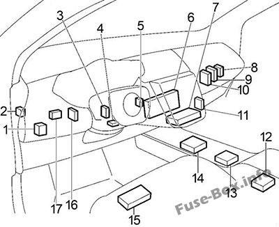
Right-hand drive vehicles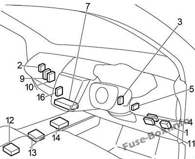
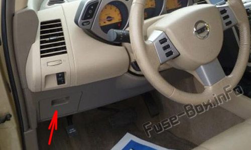
- Fuse Box (it is located on the driver’s side of the dashboard, behind the cover)

- 4WD Control Unit
- Body Control Module (BCM)
- Shift Lock Control Unit
- Nissan Anti-Theft System Immobiliser (NATS IMMU)
- Display Control Unit (with Navigation System)
- Unified Meter and A/C Amplifier
- Tire Pressure Warning Control Unit
- Transmission Control Module (TCM)
- Engine Control Module (ECM)
- Remote Keyless Entry Control Unit
- Air Bag Diagnosis Sensor Unit
- Transfer Unit
- Navigation Control Unit
- Driver Control Unit
- Time Control Unit
- Automatic Drive Positioner Control Unit
Advertisements
Engine Compartment overview
Left-hand drive vehicles 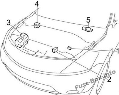
Right-hand drive vehicles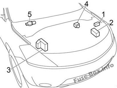
Источник
Nissan Murano Wiring Diagram Database
Nissan Murano Wiring Diagram Database.
Declining to take the correct precautions or to use the right tools can put you you in danger. Common hazards include electrocution and possible electrical fireplace.
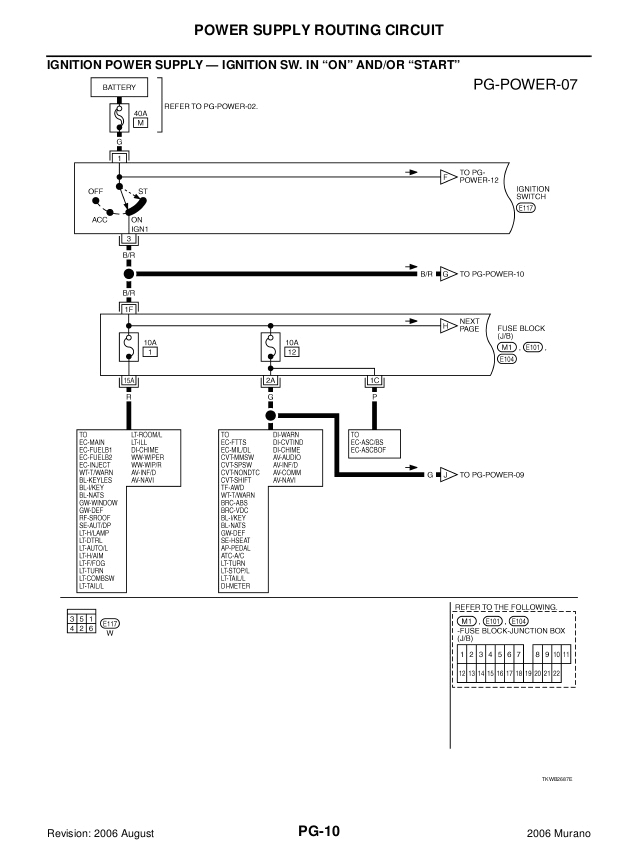
Nissan Murano Wiring Diagram
Print the wiring diagram off plus use highlighters to trace the signal. When you make use of your finger or perhaps the actual circuit with your eyes, it is easy to mistrace the circuit. 1 trick that We 2 to printing a similar wiring plan off twice. Upon one, I’ll trace the current movement, how it operates, and that exhibits me what parts of the signal I need to be able to check. Then on the other 1, I’ll start colouring the things which tested okay. When I get completed, anything that’s not necessarily highlighted are believe circuits that I want to identify.
Before reading a schematic, get common and understand all of the symbols. Read typically the schematic like a new roadmap. I printing the schematic and highlight the signal I’m diagnosing in order to make sure Im staying on right path.
Wiring Tips
Confident that you really know what you’re doing? Be sure to keep these security advice when mind to avoid hazards during your home cabling project.
1. Strength Off
Make sure the power is off at the breaker prior to starting and use a voltage tester to verify that wires and/or electrical contacts are completely lifeless before you start working on them. Make sure everyone in your home is aware that electrical work is going on. Tape the circuit breaker into the off position.
2. Be Careful What You Touch
Never touch plumbing or fuel pipes while working together with electricity they are often used to ground electrical systems.
3. Use The Right Tools
Before you begin, be sure you have an idea in place as to what outlets, switches and fixtures will be involved in your project. Create sure you have all the appropriate tools, including but not limited to: needlenose pliers, wire blades, cable & wire stripper, fish & colored tape, volts tester, continuity specialist, electric & rightangle drill. You may be capable to rent some of this equipment from your local hardware store.
4. Purchase the Right Parts
If you are installing new receptacles make sure the new ones match the wiring in your home. A AL-CU stamps means it can be used on aluminum and copper wiring. When it is unmarked or you will find a reduce through the ‘S if should only be used on copper wiring.
5. Add a Junction Box
Never splice wire connections together and hide them within a wall with no verse box — an accessible junction package should always be used to become a member of wires.
6. Replace Old Wiring That Shows Indications of Deterioration or Fraying
7. Fix Fuse and Breaker Problems
8. Don’t Overload.
Inundated outlets or expansion cords can create a fire threat.
If in doubt, check with a detailed reference book or find a professional to do the work. Even if you think you got the project right, one mistake could leave a potential fire hazard lurking in your wall space. A reputable electrical contractor understands all areas of home wiring and could be able to wire your home safely in less time than it takes you to learn.
Источник
автоэлектрик
Сайт автоэлектрика. Практика ремонта, электросхемы и т.д.


Ниссан Мурано Z51 схема генератора
На ниссан мурано Z51 применяется интеллектуальная система зарядки в которой блок управления двигателя с помощью датчика тока измеряет количество тока полученное аккумулятором от генератора и ток отданный в бортовую сеть аккумулятором. По задумке это должно улучшить топливную экономичность, снизить вибрации двигателя на холостом ходу. Правда это не очень хорошо в наших российских условиях, аккумулятор может недозаряжаться зимой.
Упрощённая схема системы зарядки ниссан мурано Z51

Блок управления двигателя замеряет ток аккумулятора с помощью датчика тока на минусовой клемме аккумуляторной батареи, в зависимости от условий работы двигателя блок управления двигателя по шине данных CAN посылает подкапотному блоку IPDM информацию о необходимом напряжении генератора. Блок IPDM управляет генератором изменяя скважность управляющего сигнала. Регулятор напряжения в генераторе изменяет выходное напряжение в зависимости от скважности этого сигнала. Также регулятор напряжения управляет контрольной лампой зарядки на панели приборов.

Расположение генератора на мурано Z51

На ниссан мурано Z51 применяется генератор A003TJ1791 производства Митсубиши. Максимальный ток генератора на мурано 130 Ампер, напряжение регулятора 14,1 — 14,7 (с возможностью регулировки в пределах 11.4 — 15.6 вольт). Сопротивление ротора генератора 1.8 — 2.2 ома.

Снятие генератора на мурано Z51

Разборка генератора ниссан мурано Z51

Проверка сопротивления ротора генератора (обмотки возбуждения)мультиметром

Для проверки обмоток статора их нужно отсоеденить от диодного моста.
Источник
Nissan Murano Wiring Diagram
Nissan Murano Wiring Diagram– wiring diagram is a simplified adequate pictorial representation of an electrical circuit. It shows the components of the circuit as simplified shapes, and the power and signal connections amongst the devices.
A wiring diagram usually gives suggestion approximately the relative slant and promise of devices and terminals upon the devices, to incite in building or servicing the device. This is unlike a schematic diagram, where the understanding of the components’ interconnections upon the diagram usually does not consent to the components’ creature locations in the curtains device. A pictorial diagram would perform more detail of the creature appearance, whereas a wiring diagram uses a more figurative notation to highlight interconnections higher than monster appearance.
A wiring diagram is often used to troubleshoot problems and to make definite that every the connections have been made and that whatever is present.
2007 nissan murano service repair manual
Architectural wiring diagrams accomplish the approximate locations and interconnections of receptacles, lighting, and remaining electrical facilities in a building. Interconnecting wire routes may be shown approximately, where particular receptacles or fixtures must be upon a common circuit.
Wiring diagrams use customary symbols for wiring devices, usually stand-in from those used on schematic diagrams. The electrical symbols not only accomplishment where something is to be installed, but after that what type of device is beast installed. For example, a surface ceiling spacious is shown by one symbol, a recessed ceiling lively has a different symbol, and a surface fluorescent open has substitute symbol. Each type of switch has a stand-in fable and as a result accomplish the various outlets. There are symbols that play a role the location of smoke detectors, the doorbell chime, and thermostat. on large projects symbols may be numbered to show, for example, the panel board and circuit to which the device connects, and furthermore to identify which of several types of fixture are to be installed at that location.
2003 nissan murano service repair manual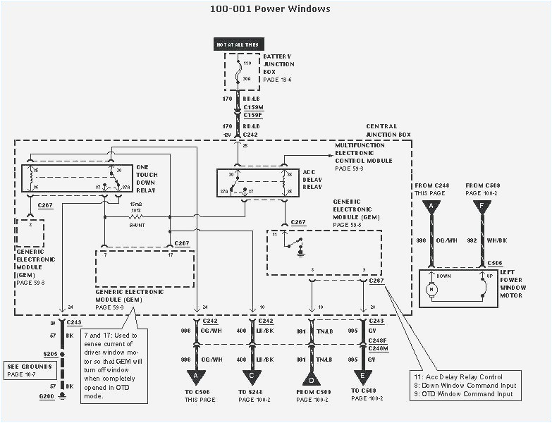
wiring diagram for 2004 murano on trailer wiring harness gmc sierra
A set of wiring diagrams may be required by the electrical inspection authority to embrace connection of the residence to the public electrical supply system.
Wiring diagrams will along with augment panel schedules for circuit breaker panelboards, and riser diagrams for special services such as flare alarm or closed circuit television or supplementary special services.
nissan murano wiring diagram another photograph:
nissan murano wiper fuse wiring diagram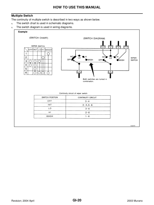
2003 nissan murano service repair manual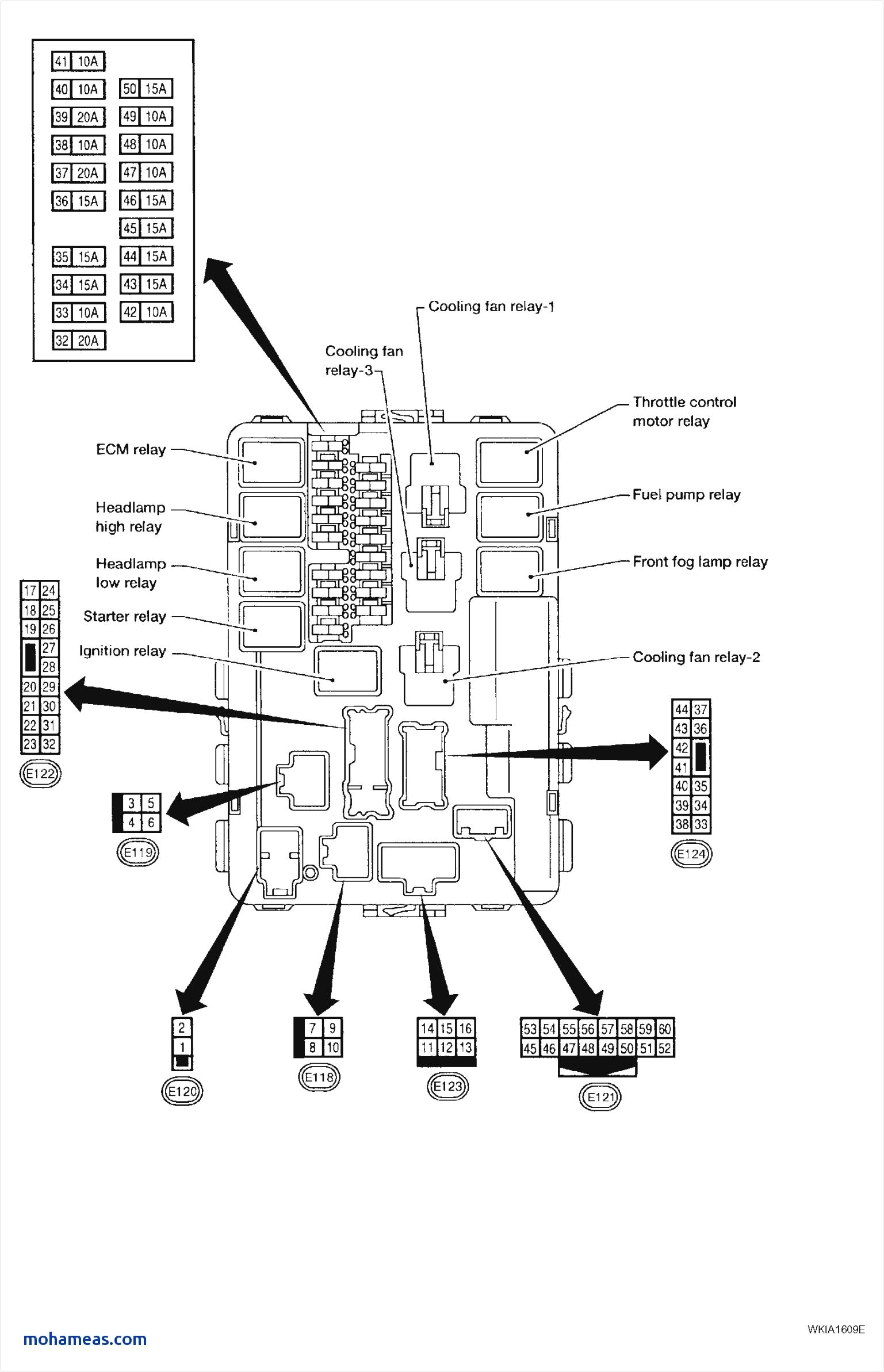
04 nissan murano fuse box wiring diagram
Источник